PICOSCOPE® 5000 SERIES
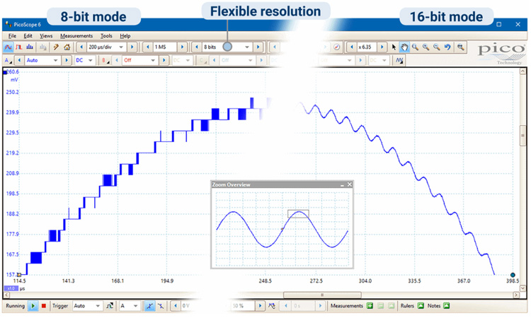
FlexRes® Oscilloscopes이러한 다양한 신호 유형을 처리하기 위해 PicoScope 5000D FlexRes 하드웨어는 다양한 시간 인터리브 및 병렬 조합의 입력 채널에서 다중 고해상도 ADC를 사용하여 샘플링 속도를 8비트에서 1GS/s로, 분해능을 16비트로 최적화합니다. 62.5 MS/s 또는 그 사이의 다른 조합에서 – 각 측정의 요구 사항에 가장 적합한 하드웨어 분해능을 선택합니다.
2 및 4 채널 모델을 사용할 수 있으며, 모두 SuperSpeed USB 3.0 연결을 지원하여 이전 USB 표준과의 호환성을 유지하면서 놀라운 빠른 파형 저장을 제공합니다. PicoSDK® 소프트웨어 개발 키트는 최대 125MS/s의 속도로 호스트 컴퓨터로의 연속 스트리밍을 지원합니다. 제품은 작고 가볍고 저전력 팬리스 설계로 조용하게 작동합니다.
무료로 정기적으로 업데이트되는 PicoScope 6 소프트웨어의 지원을 받는 PicoScope 5000D 시리즈는 설계, 연구, 테스트, 교육, 서비스 및 수리를 비롯한 많은 응용 분야에 이상적이고 비용 효율적인 패키지를 제공합니다.
주요사양 :
FlexRes란 무엇입니까?
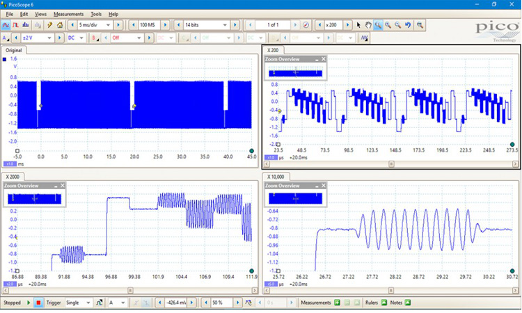
딥 캡처 메모리
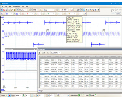
딥 메모리는 다른 방법으로도 유용할 수 있습니다. PicoScope를 사용하면 캡처 메모리를 최대 10,000개의 세그먼트로 나눌 수 있습니다. 트리거 조건을 설정하여 각 세그먼트에 별도의 캡처를 저장할 수 있습니다. 캡처 사이의 데드 타임이 1 µs입니다. 데이터를 수집한 후에는 원하는 이벤트를 찾을 때까지 메모리를 한 번에 한 세그먼트씩 이동할 수 있습니다. 이 모든 데이터를 관리하고 검사할 수 있는 강력한 도구가 포함되어 있습니다. 마스크 한계 테스트 및 색상 지속성 모드와 같은 기능뿐 아니라 PicoScope 6 소프트웨어를 사용하면 파형을 수백만 배 확대할 수 있습니다. 확대/축소 오버뷰 창을 사용하면 확대/축소 영역의 크기와 위치를 쉽게 제어할 수 있습니다.
DeepMeasureTM, 직렬 디코딩 및 하드웨어 가속과 같은 기타 도구는 딥 메모리와 함께 작동하여 PicoScope 5000D 시리즈를 시장에서 가장 강력한 오실로스코프 중 하나로 만듭니다.
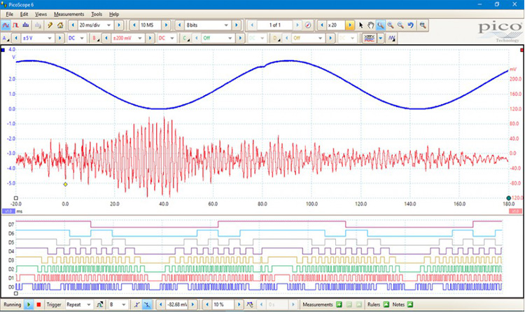
혼합 신호 모델
디지털 입력은 직렬 디코딩 옵션에 추가적인 기능을 제공합니다. 동시에 모든 아날로그 및 디지털 채널에서 직렬 데이터를 디코딩할 수 있어 최대 20개의 데이터 채널이 제공됩니다. (예: 여러 개의 SPI, I²C, CAN 버스, LIN 버스 및 FlexRay 신호를 모두 동시에 디코딩).
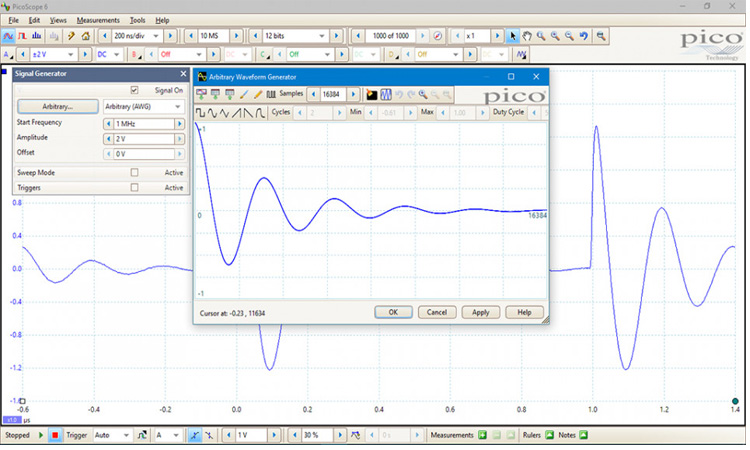
임의파형 , 함수발생기
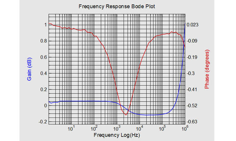
레벨, 오프셋 및 주파수를 설정하는 기본 컨트롤 외에도 더 많은 고급 컨트롤을 사용하여 다양한 주파수를 스위프할 수 있습니다. 이 기능은 스펙트럼 피크 홀드 옵션과 결합되어 증폭기 및 필터 응답을 테스트하는 강력한 도구가 됩니다. 트리거 도구를 사용하면 스코프 트리거 또는 마스크 제한 테스트 실패와 같은 다양한 조건이 충족될 경우 하나 이상의 파형 사이클을 출력할 수 있습니다.
소프트웨어 개발 키트 - 나만의 앱 작성
예제 코드는 Microsoft Excel, National Instruments LabVIEW 및 MathWorks MATLAB과 같은 타사 소프트웨어 패키지에 인터페이스하는 방법을 보여줍니다.
| [ Feature ] | |
|---|---|
고대역폭, 높은 샘플링 속도 휴대하기 좋은 크기로 가성비 좋은 제품으로 최대 200MHz의 대역폭까지 성능 저하없이 측정 가능합니다. 이 대역폭은 1GS/s의 실시간 샘플링 속도와 일치하므로 고주파수를 자세히 표시할 수 있습니다. 입력 대역폭의 5배에 달하는 실시간 샘플링 속도를 제공하는 PicoScope 5000 시리즈 오실로스코프는 고주파수 신호 세부 사항을 캡처하는 데 적합합니다. 반복 신호의 경우 ETS(등가 시간 샘플링) 모드를 사용하여 최대 유효 샘플링 속도를 10GS/s로 높일 수 있습니다. |
 |
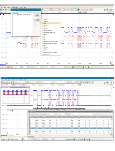 |
직렬 버스 디코딩 및 분석 딥 메모리를 사용하는 PicoScope 5000D 시리즈는 1-Wire, ARINC 429, CAN 및 CAN-FD, DALI, DCC, DMX512, 이더넷 10Base-T 및 100Base-TX, FlexRay, I²C, I²S, LIN, Manchester, MODBUS , PS/2, SENT, SPI, UART(RS-232 / RS-422 / RS-485) 및 USB 1.1 프로토콜 데이타(표준) 를 디코딩할 수 있습니다. Ecoding은 프로그래밍 및 타이밍 오류를 식별하고 다른 신호 무결성 문제를 확인하기 위해 설계에서 발생하는 문제를 찾을 수 있습니다. 타이밍 분석 도구는 전체 시스템 성능을 최적화하기 위해 개선해야 하는 설계 부분을 식별하여 각 설계 요소의 성능을 표시하는 데 도움이 됩니다. 그래프 형식은 공통 시간 축의 파형 아래에 타이밍 다이어그램 형식으로 디코딩된 데이터(16진수, 2진수, 10진수 또는 ASCII)를 표시하며 오류 프레임은 빨간색으로 표시됩니다. 이 프레임을 확대하여 노이즈 또는 왜곡을 조사할 수 있으며 각 패킷 필드에는 다른 색상이 할당되므로 데이터를 쉽게 읽을 수 있습니다. 테이블 형식은 데이터와 모든 플래그 및 식별자를 포함하여 디코딩된 프레임 목록을 보여줍니다. 원하는 프레임만 표시하거나 속성이 지정된 프레임을 검색하도록 필터링 조건을 설정할 수 있습니다. 통계 옵션은 프레임 시간 및 전압 레벨과 같은 물리적 계층에 대한 자세한 정보를 보여줍니다. PicoScope는 스프레드시트를 가져와 데이터를 사용자 정의 텍스트 문자열로 디코딩할 수도 있습니다. |
DeepMeasure One waveform, millions of measurements 파형 펄스 및 주기의 측정은 전기 및 전자 장치의 성능을 검증하는 데 중요합니다. DeepMeasure는 트리거된 각 수집과 함께 최대 백만 파형 주기에서 중요한 파형 매개변수의 자동 측정을 제공합니다. 결과는 파형 디스플레이와 쉽게 정렬, 분석 및 관련성를 확인하실 수 있습니다. |
 |
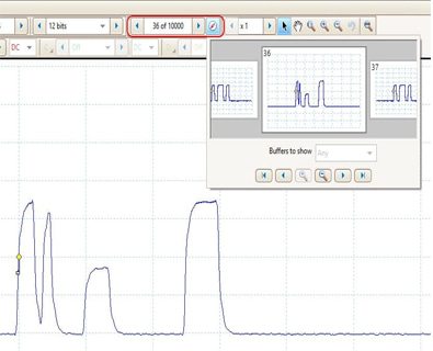 |
파형 버퍼와 네비게이터 파형에서 글리치를 발견했지만 스코프를 중지할때가지 글리치가 사라졌습니까? PicoScope라면 글리치를 놓치거나 다른 과도현상을 걱정할 필요가 없습니다. PicoScope는 원형 파형 버퍼에 마지막 만개의 오실로스코프 혹은 스펙트럼 파형을 저장할 수 있습니다. 버퍼 네비게이터는 네비게이팅과 파형 검색의 효과를 제공하며, 효과적으로 시간을 되돌릴 수 있습니다. 마스크 제한 테스트 같은 툴로 버퍼의 각 파형을 스캔하여 마스크 위반을 찾을 수 있습니다 |
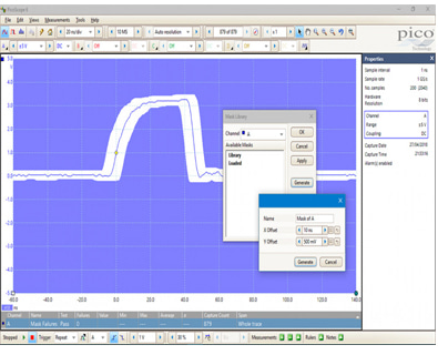
마스크 제한 테스트 마스크 제한 테스트를 통해 라이브 신호를 양호한 신호와 비교할 수 있으며 프로덕션과 디버깅 환경을 위해 설계되었습니다. 간단히 양호한 신호를 캡쳐하고, 마스크를 주변에 그리고, 그런 다음 테스트 중인 시스템에 연결합니다. PicoScope는 마스크 위반을 체크하고 성공/실패 테스트를 수행하고, 간헐적인 글릿치를 캡쳐하고, 측정 윈도우창에 실패 횟수와 다른 통계를 보여줍니다. |
 |
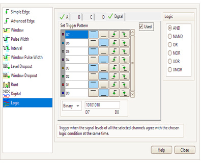 |
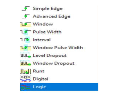
고급 디지털 트리거링 PicoScope 5000D 시리즈는 펄스 폭, 런트 펄스, 윈도우 및 드롭아웃을 포함한 업계 최고의 고급 트리거 세트를 제공합니다. MSO 모델에서 사용할 수 있는 디지털 트리거를 사용하면 16개의 디지털 입력 중 일부 또는 전부 사용자 정의 패턴과 일치할 때 스코프를 트리거할 수 있습니다. 각 채널에 개별적으로 조건을 지정하거나 16진수 또는 2진수 값을 사용하여 모든 채널에 대한 패턴을 한 번에 설정할 수 있습니다. 로직 트리거를 사용하여 아날로그 입력의 에지 또는 윈도우 트리거와 디지털 트리거를 결합할 수도 있습니다(예: 클럭 병렬 버스의 데이터 값에 대해 트리거) |
디지털 트리거링 아키텍처 대부분의 디지털 오실로스코프는 여전히 비교기를 기반으로 하는 아날로그 트리거 아키텍처를 사용합니다. 이로 인해 항상 보정할 수 없는 시간 및 진폭 오류가 발생하고 종종 고대역폭에서 트리거 감도가 제한됩니다. 1991년 Pico는 실제 디지털화된 데이터를 사용하여 완전한 디지털 트리거링의 사용을 개척했습니다. 이 기술은 트리거 오류를 줄이고 오실로스코프가 전체 대역폭에서도 가장 작은 신호에서 트리거할 수 있도록 합니다. 트리거 레벨 및 히스테리시스(hysteresis)는 고정밀 및 분해능으로 설정할 수 있습니다. 세그먼트 메모리와 함께 디지털 트리거링이 제공하는 1µs 미만의 재설정 지연을 통해 10ms 버스트에서 최대 10,000개의 파형을 캡처할 수 있습니다. PicoScope 5000D MSO 모델에서 디지털 채널을 사용하여 부울(Boolean) 연산자로 로직 트리거를 형성할 수 있습니다. |
 |
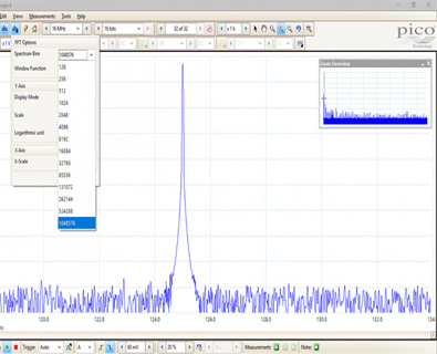 |
FFT spectrum analyzer 스펙트럼 보기는 주파수에 대한 진폭을 표시하며 신호의 노이즈, 누화 또는 왜곡을 찾는 데 이상적입니다. PicoScope의 스펙트럼 분석기는 기존의 스위프 스펙트럼 분석기와 달리 단일 비반복 파형의 스펙트럼을 표시할 수 있는 FFT( Fast Fourier Transform) 유형입니다. 전체 범위의 설정을 통해 스펙트럼 대역(FFT bins), 창 유형, 스케일링( including log/log ) 및 디스플레이 모드( instantaneous, average, or peak-hold)의 수를 제어할 수 있습니다. 동일한 데이터의 오실로스코프 보기(Views)와 함께 여러 스펙트럼 보기(Views)를 표시할 수 있습니다. THD, THD+N, SNR, SINAD 및 IMD를 포함한 포괄적인 자동 주파수 영역 측정 세트를 디스플레이에 추가할 수 있습니다. 마스크 한계 테스트를 스펙트럼에 적용할 수 있으며 AWG와 스펙트럼 모드를 함께 사용하여 스윕 스칼라 네트워크 분석(swept scalar network analysis)을 수행할 수도 있습니다. |
아래의 table에서 PICOSCOPE® 5000 SERIES 의 모델을 확인하세요.
| Model | PicoScope | |||||
|---|---|---|---|---|---|---|
| Bandwidth (–3 dB) | 60 MHz | 100 MHz | 200 MHz | |||
| 2 channel | 5242D | 5242D MSO | 5243D | 5243D MSO | 5244D | 5244D MSO |
| 4 channel | 5442D | 5442D MSO | 5443D | 5443D MSO | 5444D | 5444D MSO |
| Oscilloscope - vertical | ||||||
|---|---|---|---|---|---|---|
| Input type | Single-ended, BNC connector | |||||
| Bandwidth (–3 dB) | 60 MHz | 100 MHz[1] | 200 MHz[1] | |||
| Rise time (calculated) | 5.8 ns | 3.5 ns[1] | 1.75 ns[1] | |||
| Bandwidth limiter | 20 MHz, selectable | |||||
| Vertical resolution[2] | 8, 12, 14, 15 or 16 bits | |||||
| LSB size[2] (quantization step size) | 8 bit mode: < 0.6% of input range 12 bit mode: < 0.04% of input range 14 bit mode: < 0.01% of input range 15 bit mode: < 0.005% of input range 16 bit mode: < 0.0025% of input range |
|||||
| Enhanced vertical resolution | Hardware resolution + 4 bits | |||||
| Input ranges | ±10 mV to ±20 V full scale, in 11 ranges | |||||
| Input sensitivity | 2 mV/div to 4 V/div (10 vertical divisions) | |||||
| Input coupling | AC / DC | |||||
| Input characteristics | 1 MΩ ± 1% || 14 ±1 pF | |||||
| Gain accuracy | 12 to 16 bit modes: ±0.5% of signal ±1 LSB[3] 8 bit mode: ±2% of signal ±1 LSB[3] |
|||||
| Offset accuracy | ±500 µV ±1% of full scale[3] Offset accuracy can be improved by using the “zero offset” function in PicoScope 6. |
|||||
| Analog offset range (vertical position adjust) | ±250 mV (10, 20, 50, 100, 200 mV ranges), ±2.5 V (500 mV, 1 V, 2 V ranges), ±20 V (5, 10, 20 V ranges) |
|||||
| Analog offset control accuracy | ±0.5% of offset setting, additional to basic DC offset accuracy | |||||
| Overvoltage protection | ±100 V (DC + AC peak) | |||||
[1] In 16-bit mode, bandwidth reduced to 60 MHz and rise time increased to 5.8 ns.
[2] On ±20 mV range, in 14 to 16-bit modes, hardware resolution reduced by 1 bit. On ±10 mV range, hardware resolution reduced by 1 bit in 12-bit mode, 2 bits in 14 to 16-bit modes.
[3] Between 15 and 30 °C after 1 hour warm-up.
| Vertical (digital channels) – D MSO models only | ||||||
|---|---|---|---|---|---|---|
| Input channels | 16 channels (2 ports of 8 channels each) | |||||
| Input connector | 2.54 mm pitch, 10 x 2 way connector | |||||
| Maximum input frequency | 100 MHz (200 Mbit/s) | |||||
| Minimum detectable pulse width | 5 ns | |||||
| Input impedance | 200 kΩ ±2% || 8 pF ±2 pF | |||||
| Input dynamic range | ±20 V | |||||
| Threshold range | ±5 V | |||||
| Threshold grouping | Two independent threshold controls. Port 0: D0 to D7, Port 1: D8 to D15 | |||||
| Threshold selection | TTL, CMOS, ECL, PECL, user-defined | |||||
| Threshold accuracy | < ±350 mV including hysteresis | |||||
| Threshold hysteresis | < ±250 mV | |||||
| Minimum input voltage swing | 500 mV peak to peak | |||||
| Channel-to-channel skew | 2 ns, typical | |||||
| Minimum input slew rate | 10 V/µs | |||||
| Overvoltage protection | ±50 V (DC + AC peak) | |||||
| Horizontal | |||||||||||
|---|---|---|---|---|---|---|---|---|---|---|---|
| Max. sampling rate Any 1 channel Any 2 channels Any 3 or 4 channels More than 4 channels |
[4]Any number of 8-bit digital ports can be used in 15-bit and 16-bit modes without affecting the maximum sampling rate |
||||||||||
| Maximum equivalent sampling rate (repetitive signals; 8-bit mode only, ETS mode) | 2.5 GS/s | 5 GS/s | 10 GS/s | ||||||||
| Maximum sampling rate (continuous USB streaming into PC memory)[5] | USB 3, using PicoScope 6: 15 to 20 MS/s USB 3, using PicoSDK: 125 MS/s (8-bit) or 62.5 MS/s (12 to 16 bit modes) USB 2, using PicoScope 6: 8 to 10 MS/s USB 2, using PicoSDK: ~30 MS/s (8-bit) or ~15 MS/s (12 to 16 bit modes) |
||||||||||
| Timebase ranges (real time) | 1 ns/div to 5000 s/div in 39 ranges | ||||||||||
| Fastest timebase (ETS) | 500 ps/div | 200 ps/div | 100 ps/div | ||||||||
| Buffer memory[6] (8-bit mode) | 128 MS | 256 MS | 512 MS | ||||||||
| Buffer memory[6] (≥ 12-bit mode) | 64 MS | 128 MS | 256 MS | ||||||||
| Buffer memory[7] (continuous streaming) | 100 MS in PicoScope software | ||||||||||
| Waveform buffer (no. of segments) | 10 000 in PicoScope software | ||||||||||
| Waveform buffer (no. of segments) when using PicoSDK (8 bit mode) | 250 000 | 500 000 | 1 000 000 | ||||||||
| Waveform buffer (no. of segments) when using PicoSDK (12 to 16 bit modes) | 125 000 | 250 000 | 500 000 | ||||||||
| Initial timebase accuracy | ±50 ppm (0.005%) | ±2 ppm (0.0002%) | ±2 ppm (0.0002%) | ||||||||
| Timebase drift | ±5 ppm/year | ±1 ppm/year | ±1 ppm/year | ||||||||
| Sample jitter | 3 ps RMS, typical | ||||||||||
| ADC sampling | Simultaneous on all enabled channels | ||||||||||
[5]Shared between enabled channels, PC dependent, available sample rates vary by resolution.
[6]Shared between enabled channels.
[7]Driver buffering up to available PC memory when using PicoSDK. No limit on duration of capture.
| Dynamic performance (typical; analog channels) | ||||||
|---|---|---|---|---|---|---|
| Crosstalk | Better than 400:1 up to full bandwidth (equal voltage ranges) | |||||
| Harmonic distortion |
8-bit mode: −60 dB at 100 kHz full scale input. |
|||||
| SFDR | 8 to 12-bit modes: 60 dB at 100 kHz full scale input. 14 to 16-bit modes: 70 dB at 100 kHz full scale input. |
|||||
| Noise (on most sensitive range) | 8-bit mode: 120 μV RMS 12-bit mode: 110 μV RMS 14-bit mode: 100 μV RMS 15-bit mode: 85 μV RMS 16-bit mode: 70 μV RMS |
|||||
| Bandwidth flatness | (+0.3 dB, –3 dB) from DC to full bandwidth | |||||
| Triggering (main specifications) | ||||||
|---|---|---|---|---|---|---|
| Source | Analog channels, plus: MSO models: Digital D0 to D15. Other models: Ext trigger. | |||||
| Trigger modes | None, auto, repeat, single, rapid (segmented memory). | |||||
| Advanced trigger types (analog channels) | Edge, window, pulse width, window pulse width, dropout, window dropout, interval, runt, logic. | |||||
| Trigger types (analog channels, ETS) | Rising or falling edge ETS trigger available on ChA only, 8-bit mode only. | |||||
| Trigger sensitivity (analog channels) | Digital triggering provides 1 LSB accuracy up to full bandwidth of scope. | |||||
| Trigger sensitivity (analog channels, ETS) | At full bandwidth: typical 10 mV peak to peak | |||||
| Trigger types (digital inputs) | MSO models only: Edge, pulse width, dropout, interval, logic, pattern, mixed signal. | |||||
| Maximum pre-trigger capture | Up to 100% of capture size. | |||||
| Maximum post-trigger delay | Zero to 4 billion samples, settable in 1 sample steps (delay range on fastest timebase of 0 – 4 s in 1 ns steps) | |||||
| Trigger rearm time | 8-bit mode, typical: 1 μs on fastest timebase 8 to 12 bit modes: < 2 μs max on fastest timebase 14 to 16 bit modes: < 3 μs max on fastest timebase |
|||||
| Maximum trigger rate | 10 000 waveforms in a 10 ms burst, 8-bit mode | |||||
| External trigger input – not MSO models | ||||||
|---|---|---|---|---|---|---|
| Connector type | Front panel BNC | |||||
| Trigger types | Edge, pulse width, dropout, interval, logic | |||||
| Input characteristics | 1 MΩ ± 1% || 14 pF ±1.5 pF | |||||
| Bandwidth | 60 MHz | 100 MHz | 200 MHz | |||
| Threshold range | ±5 V | |||||
| Threshold range | ±5 V, DC coupled | |||||
| External trigger threshold accuracy | ±1% of full scale | |||||
| External trigger sensitivity | 200 mV peak to peak | |||||
| Coupling | DC | |||||
| Overvoltage protection | ±100 V (DC + AC peak) | |||||
| Function generator | ||||||
|---|---|---|---|---|---|---|
| Standard output signals | Sine, square, triangle, DC voltage, ramp up, ramp down, sinc, Gaussian, half-sine | |||||
| Pseudorandom output signals | White noise, selectable amplitude and offset within output voltage range. Pseudorandom binary sequence (PRBS), selectable high and low levels within output voltage range, selectable bit rate up to 20 Mb/s |
|||||
| Standard signal frequency | 0.025 Hz to 20 MHz | |||||
| Sweep modes | Up, down, dual with selectable start / stop frequencies and increments | |||||
| Triggering | Can trigger a counted number of waveform cycles or frequency sweeps (from 1 to 1 billion) from the scope trigger, external trigger or from software. Can also use the external trigger to gate the signal generator output. | |||||
| Output frequency accuracy | Oscilloscope timebase accuracy ± output frequency resolution | |||||
| Output frequency resolution | < 0.025 Hz | |||||
| Output voltage range | ±2 V | |||||
| Output voltage adjustments | Signal amplitude and offset adjustable in approx 0.25 mV steps within overall ±2 V range | |||||
| Amplitude flatness | < 1.5 dB to 20 MHz, typical | |||||
| DC accuracy | ±1% of full scale | |||||
| SFDR | > 70 dB, 10 kHz full scale sine wave | |||||
| Output resistance | 50 Ω ±1% | |||||
| Connector type | BNC(f) | |||||
| Overvoltage protection | ±20 V | |||||
| Arbitrary waveform generator | ||||||
|---|---|---|---|---|---|---|
| AWG update rate | 200 MHz | |||||
| AWG buffer size | 32 kS | |||||
| AWG resolution | 14 bits (output step size approximately 0.25 mV) | |||||
| AWG bandwidth | > 20 MHz | |||||
| AWG rise time (10% to 90%) | < 10 ns (50 Ω load) | |||||
Additional AWG specifications including sweep modes, triggering, frequency accuracy and resolution, voltage range, DC accuracy and output characteristics are as the function generator
| Probe compensation pin | ||||||
|---|---|---|---|---|---|---|
| Output characteristics | 600 Ω | |||||
| Output frequency | 1 kHz | |||||
| Output level | 3 V peak to peak, typical | |||||
| Overvoltage protection | 10 V | |||||
| Spectrum analyzer | ||||||
|---|---|---|---|---|---|---|
| Frequency range | DC to 60 MHz | DC to 100 MHz | DC to 200 MHz | |||
| Display modes | Magnitude, average, peak hold | |||||
| Y axis | Logarithmic (dbV, dBu, dBm, arbitrary dB) or linear (volts) | |||||
| X axis | Linear or logarithmic | |||||
| Windowing functions | Rectangular, Gaussian, triangular, Blackman, Blackman–Harris, Hamming, Hann, flat-top | |||||
| Number of FFT points | Selectable from 128 to 1 million in powers of 2 | |||||
| Math channels | ||||||
|---|---|---|---|---|---|---|
| Functions | −x, x+y, x−y, x*y, x/y, x^y, sqrt, exp, ln, log, abs, norm, sign, sin, cos, tan, arcsin, arccos, arctan, sinh, cosh, tanh, delay, average, frequency, derivative, integral, min, max, peak, duty, highpass, lowpass, bandpass, bandstop | |||||
| Operands | A, B, C, D (input channels), T (time), reference waveforms, pi, D0−D15 (digital channels), constants | |||||
| Automatic measurements | ||||||
|---|---|---|---|---|---|---|
| Scope mode | AC RMS, true RMS, frequency, cycle time, duty cycle, DC average, falling rate, rising rate, low pulse width, high pulse width, fall time, rise time, minimum, maximum, peak to peak | |||||
| Spectrum mode | Frequency at peak, amplitude at peak, average amplitude at peak, total power, THD %, THD dB, THD+N, SFDR, SINAD, SNR, IMD | |||||
| Statistics | Minimum, maximum, average, standard deviation | |||||
| DeepMeasure™ | ||||||
|---|---|---|---|---|---|---|
| Parameters | Cycle number, cycle time, frequency, low pulse width, high pulse width, duty cycle (high), duty cycle (low), rise time, fall time, undershoot, overshoot, max. voltage, min. voltage, voltage peak to peak, start time, end time | |||||
| Serial decoding | ||||||
|---|---|---|---|---|---|---|
| Protocols | 1-Wire, ARINC 429, CAN, CAN FD, DALI, DCC, DMX512, Ethernet 10Base-T and 100Base-TX, FlexRay, I²C, I²S, LIN, Manchester, MODBUS, PS/2, MODBUS, SENT, SPI, UART (RS-232 / RS-422 / RS-485), USB 1.1 | |||||
| Mask limit testing | ||||||
|---|---|---|---|---|---|---|
| Statistics | Pass/fail, failure count, total count | |||||
| Mask creation | User-drawn, table entry, auto-generated from waveform or imported from file | |||||
| Display | ||||||
|---|---|---|---|---|---|---|
| Interpolation | Linear or sin(x)/x | |||||
| Persistence modes | Digital color, analog intensity, custom, fast | |||||
| Software | ||
|---|---|---|
| Windows software | PicoScope for Windows For Windows 7, 8 and 10 |
|
| macOS software | PicoScope for macOS (beta: feature list) Software development kit (SDK) OS versions: see release notes |
|
| Linux software | PicoScope for Linux (beta: feature list) Software development kit (SDK) See Linux Software & Drivers for details of supported distributions |
|
| Languages | Chinese (simplified), Chinese (traditional), Czech, Danish, Dutch, English, Finnish, French, German, Greek, Hungarian, Italian, Japanese, Korean, Norwegian, Polish, Portuguese, Romanian, Russian, Spanish, Swedish, Turkish | |
| General | ||||||
|---|---|---|---|---|---|---|
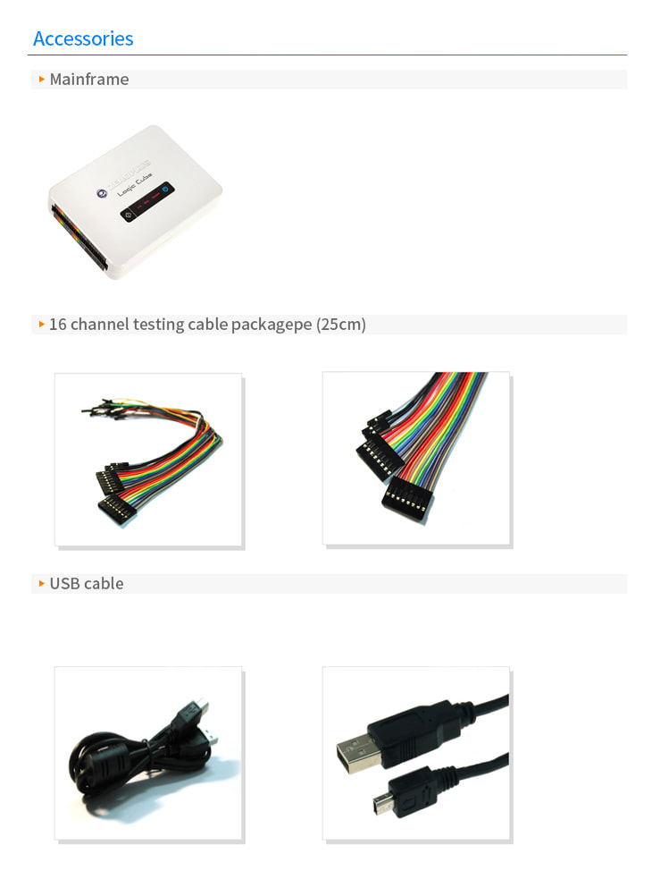
| Package contents | PicoScope 5000D Series oscilloscope 1 x TA155 Pico blue USB 3 cable 1.8 m 60 MHz models: 2/4 x TA375 probes 100 MHz models: 2/4 x TA375 probes 200 MHz models: 2/4 x TA386 probes 4-channel models: 1 x PS011 5 V 3.0 A PSU MSO models: 1 x TA136 MSO cable MSO models: 2 x TA139 set of MSO clips Quick start guide |
|||||
| PC connectivity | USB 3.0 SuperSpeed (USB 2.0 compatible) | |||||
| Power requirements | 2-channel models: powered from single USB 3.0 port 4-channel models: AC adaptor supplied. Can use 2 channels (plus MSO channels if fitted) powered by USB 3.0 or charging port supplying 1.2 A. |
|||||
| Dimensions | 190 x 170 x 40 mm including connectors | |||||
| Weight | < 0.5 kg | |||||
| Temperature range | Operating: 0 to 40 °C 15 to 30 °C for quoted accuracy after 1 hour warm-up Storage: –20 to +60 °C |
|||||
| Humidity range | Operating: 5 to 80 %RH non-condensing Storage: 5 to 95 %RH non-condensing |
|||||
| Environment | Up to 2000 m altitude and EN61010 pollution degree 2 | |||||
| Safety approvals | Designed to EN 61010-1:2010 | |||||
| EMC approvals | Tested to EN61326-1:2013 and FCC Part 15 Subpart B | |||||
| Environmental approvals | RoHS and WEEE compliant | |||||
| PC requirements | Processor, memory and disk space: as required by the operating system Port(s): USB 3.0 or USB 2.0 |
|||||
| Warranty | - years | |||||
악세사리